Buy Yamaha Outboard Parts

Announcement

Collapse
No announcement yet.

90 hp 4 stroke electrical signals

Collapse
X
 
  • Filter
  • Time
  • Show
Clear All
new posts

  • 90 hp 4 stroke electrical signals

    Does anyone know the signal formats for various outputs from a 2003 90HP 4 stroke? I am particularly interested in the tachometer output. My tach is an analog unit that accepts Pulse per revolution signals from 2 to 6 PPR. Is this compatible with my motor output? I would also like to know what the trim output signal format is. I think it is a DC voltage but not sure.
    Thanks for any info you can provide!

  • #2
    Your alternator tac output is ac.. The charge output is 12dvc. Something you should not need to know about, Under normal situations
    Last edited by Keithbaja; 04-29-2023, 05:31 PM.

    Comment


    • #3
      Trim angle and up and down is 12vdc... If you must ask.. Don't Touch it !! Your Way over you head and pay grade

      Comment


      • #4
        He can ask, but for what purpose? None of those instruments output anything other than to their respective displays.
        Are you asking what type of non Yamaha instruments can be connected to that outboard because you don’t have any?

        Comment


        • #5
          You can connect your tachometer with a coil from a spark lead without using the engines output. With correct switch position.
          Trim and tilt are usually a reostat which uses a 3wire, top +12v bottom -12v dividing the voltage. Or they are just used as a 2wire resistor, the problem with that arrangement is the resistance needs to be known if connected to an anologe (can be digital display) ie need to be compatible on how they interpret the 12v (lessening voltage) on the trim resister.

          Comment


          • #6
            ignition spark pulse (I/Os & inboards) Diesel and most Outboards are AC charge pulse sensed..Tilt & Trim are 12vdc.. no resisters or rheostats ever have been used for up or down. Only for sending trim level units....

            Comment


            • #7
              Yes, but I think the OP wasn’t wondering what the power source the T/T uses, rather what the tilt position sender puts out.

              Definitely a rheostat or variable resister dividing 12v! Mine’s of the order 20ohms I think. Inside the sender is a round wirewound resister that has a brush slider on it. Wires from one or both ends and from the movable wiper (3wire is a rheostat, 2 wires is a variable resister)
              The wires don’t go to or from the engine as such, only out through a loom. The sender is an external unit under the tilt tube moved by a small lever attached to it.

              Sorry there will always be language differences.
              Last edited by zenoahphobic; 04-29-2023, 09:28 PM.

              Comment


              • #8
                And Bajakeith, rheostats in T/T systems reminds me that it would be good if there was the ability on outboards, to dial or set a tilt or trim position, rather than pressing a momentary switch and watching a display to the desired point, and then release. I think there are automatic engines up on switch off options available.
                Last edited by zenoahphobic; 04-29-2023, 09:50 PM.

                Comment


                • #9
                  Originally posted by windaveski View Post
                  Does anyone know the signal formats for various outputs from a 2003 90HP 4 stroke? I am particularly interested in the tachometer output. My tach is an analog unit that accepts Pulse per revolution signals from 2 to 6 PPR. Is this compatible with my motor output? I would also like to know what the trim output signal format is. I think it is a DC voltage but not sure.
                  Thanks for any info you can provide!
                  A 2003 F90 provides alternating current (AC) pulses from what Yamaha calls the "lighting"coil to drive the tachometer. The tachometer should be set to the "12 pole" position for a Yamaha tachometer. Probably the 6 position for your tachometer. Too bad the model and the brand of the tachometer is not known.

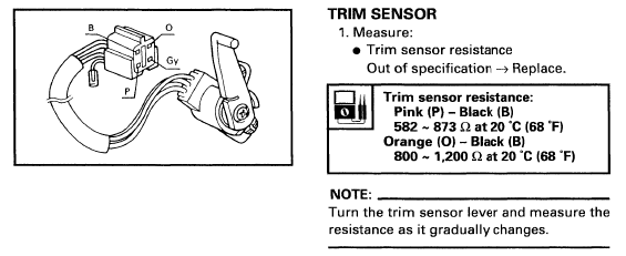
                  The 2003 F90 uses a three wire trim sender. A potentiometer. A Yamaha tachometer provides 5 volts to the sender. The sender varies that voltage as a function of the trim sender setting and sends the voltage to the tachometer.


                  Comment


                  • #10
                    The tach dosn't supply the 5V ref signal. Its sent from the ECU. Thru the tach harness. Old school tech. Thats still in use today. All cars, trucks, tractor. Buses, boats use this system.. Look up CAN BUS if your want to learn this simple tec that surrounds you...

                    Comment


                    • #11
                      Thanks for the answers. I am not very familiar with outboards but I do have 30 years experience as an electronics engineer working on jet airplanes. Given the right information I can figure out what to do with it. I am asking about motor outputs not instrument outputs. From what I see above I think the TT should work but may be scaled wrong. I will investigate further. As for the tach, I assume that the pulse type signal is essentially a square wave and the indicator uses a frequency counter to interpret the signal. If the tach output from my motor is an AC signal from the alternator I would again think that the tach uses a frequency counter. The questions would then be if the frequencies of the pulse and AC signals are anywhere close and whether the input filters in the tach are compatible with both waveforms. I am not expecting answers to these questions.
                      I did hook up the tach yesterday. It sort of works but not correctly. With the adjustment on the tach set to 2 PPR the tach reads correctly at idle but only 3500 at WOT. As I adjust the tach toward higher PPR it very suddenly reads about double the actual RPM at idle and over 6500 at WOT.
                      Again, thanks for your responses.

                      Comment


                      • #12
                        Originally posted by Keithbaja View Post
                        The tach dosn't supply the 5V ref signal. Its sent from the ECU. Thru the tach harness. Old school tech. Thats still in use today. All cars, trucks, tractor. Buses, boats use this system.. Look up CAN BUS if your want to learn this simple tec that surrounds you...
                        A 2003 F90 has carburetors. No ECU. A Capacitor Discharge Ignition (CDI) box. No CAN BUS.

                        Orange wire from the tachometer provides the 5 volts to the trim sender.

                        Comment


                        • #13
                          Originally posted by windaveski View Post
                          Thanks for the answers. I am not very familiar with outboards but I do have 30 years experience as an electronics engineer working on jet airplanes. Given the right information I can figure out what to do with it. I am asking about motor outputs not instrument outputs. From what I see above I think the TT should work but may be scaled wrong. I will investigate further. As for the tach, I assume that the pulse type signal is essentially a square wave and the indicator uses a frequency counter to interpret the signal. If the tach output from my motor is an AC signal from the alternator I would again think that the tach uses a frequency counter. The questions would then be if the frequencies of the pulse and AC signals are anywhere close and whether the input filters in the tach are compatible with both waveforms. I am not expecting answers to these questions.
                          I did hook up the tach yesterday. It sort of works but not correctly. With the adjustment on the tach set to 2 PPR the tach reads correctly at idle but only 3500 at WOT. As I adjust the tach toward higher PPR it very suddenly reads about double the actual RPM at idle and over 6500 at WOT.
                          Again, thanks for your responses.
                          and still no info on what tach you have for some reason?

                          and did you try it on 6 like Boscoe mentioned?

                          Comment


                          • #14
                            It’s probably the AC waveform is not “notchy “enough ie the tachometer can’t change it to square wave, and looses it at different speeds. I think you know what I’m saying, you made need fit circuitry that changes the waveform to the tach. Signal strength may also be an issue. Good luck.

                            Comment


                            • #15
                              The tach is a BRP/OMC 174887. It has a sticker on it that says: For use on 5 . 6 pul/rev alternator equipped outboards and 6 pul/rev OMC sea drive engines. However it has a control on the back that is labled pul/rev and has positions for 2, 3, 4, 5, 6. The control is continuously variable, i.e no detents or fixed switch positions.

                              I agree that signal strength may be an issue. The input impedance of the tach measures at 870 ohms. I plan to get some resistors to drop the voltage of the input and see if this helps.

                              I have the same manual with the trim sensor picture that boscoe99 provided. However on my motor there is no orange wire, only pink and black. I found two different sources that say earlier motors used 3 wire sensors but later ones (including my 2003) use only 2 wires. My gauge is also only 2 wires. I have not hooked it up yet but plan to do so.

                              I have some files with the trim info as above but I have not yet figured out how to attach them to this post. I am sure it is simple but I have not found the right button yet.

                              Comment

                              Working...
                              X