Good evening,
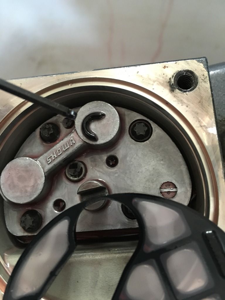
Well issues with the dealership again. (2004 Vmax HDPI) Took my trim tilt unit in to get weeping seals replaced. Came out of the shop with the trim not holding back when in reverse. I have read through the posts and it is obviously the seat balls in the pump assembly. My problem is that I did not take it apart so I do not know where the small and the large balls are placed. One small ball is missing after the repair at the certified Yamaha dealer.... And it seems two parts (piston shuttles) 7&8 on the parts diagram where installed upside down in the holes with no balls under them as in the parts schematic, and one mystery o ring from where only the mechanic knows. As you can see in the first picture one of the seat balls was in a gear, shake my head.
[IMG]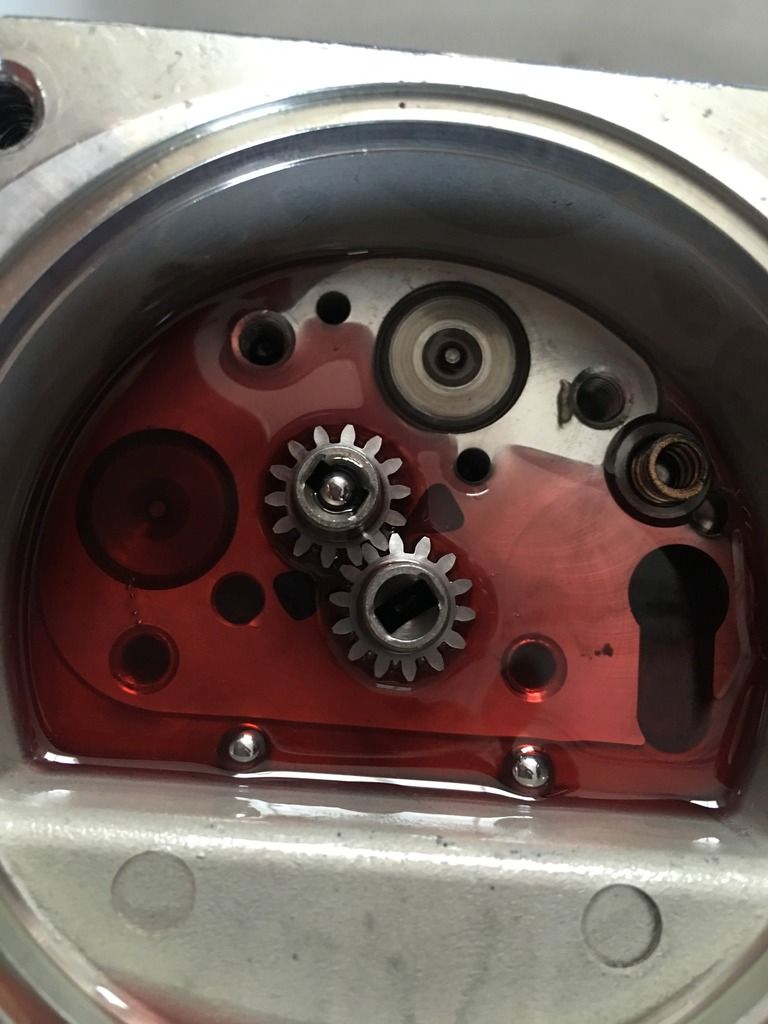 [/IMG]
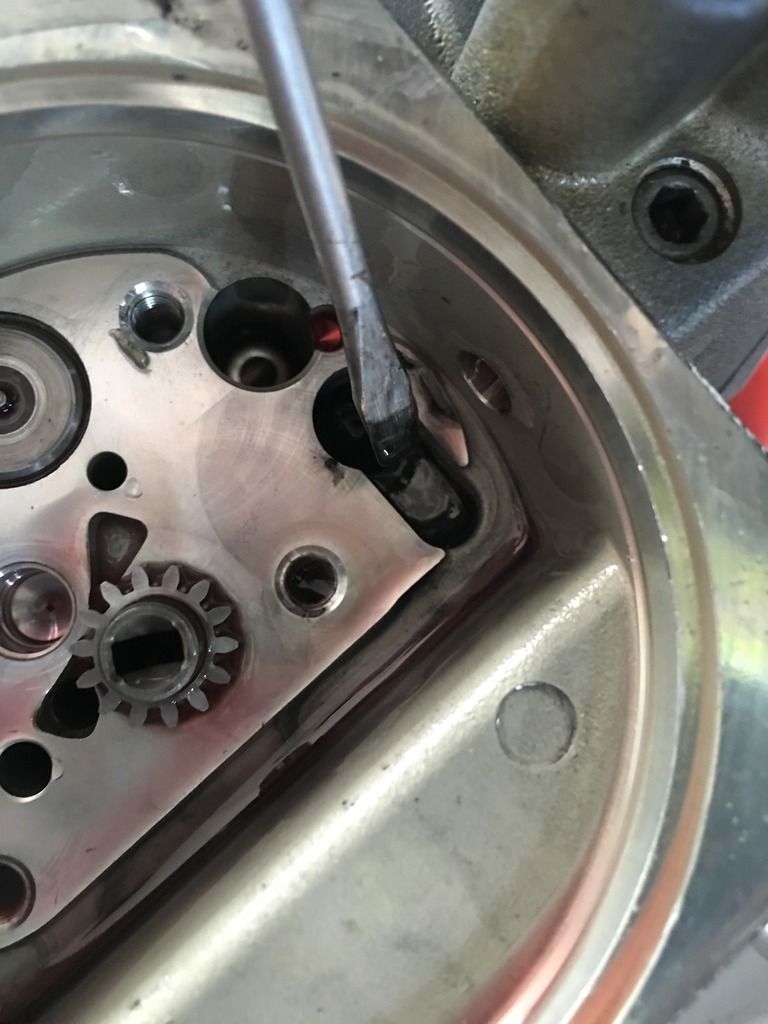
The shuttle two valves in the picture below appear to be installed upside down, no balls under them, should they be the large or the small balls? The parts diagram is a bit confusing regarding the shuttles / valve sub Assy. There are two pieces in the parts schematic but mine appear to be one solids piece, perhaps pressed together?
[IMG]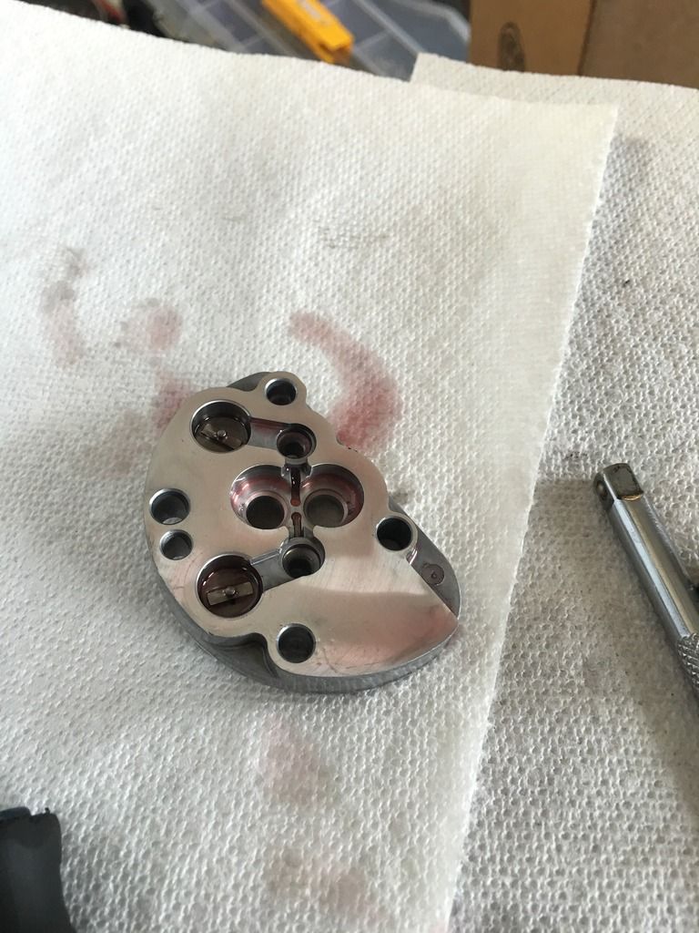 [/IMG]
Any way does anyone know if the small balls go under the valves, or do the larger balls go under the valves with the smaller on top? (Small 5 or 18 on the parts diagram?)
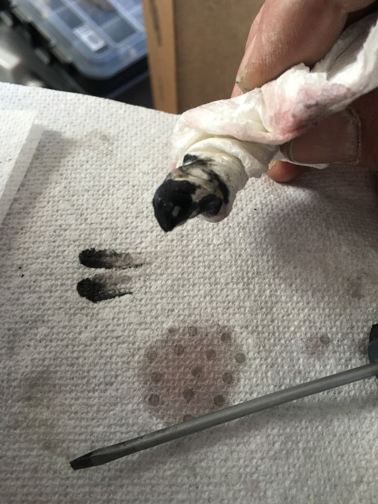
Picture of the Shuttles
[IMG]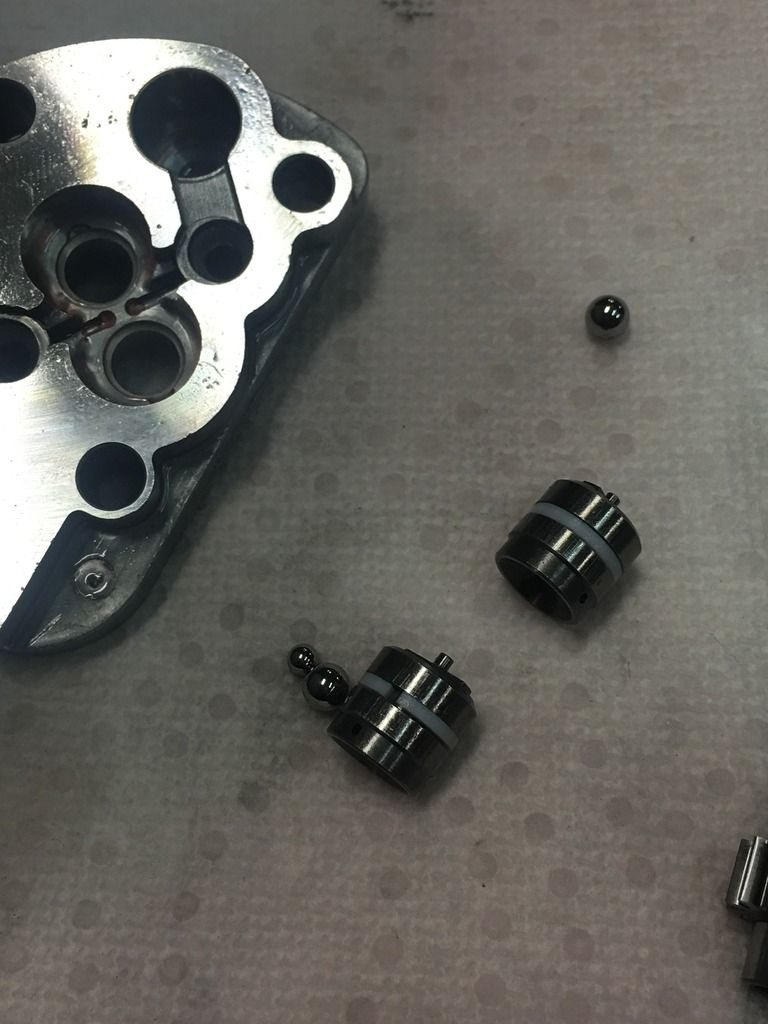 [/IMG]
Part diagram does not show if the balls are small or large and the that the valves are two pieces
[IMG]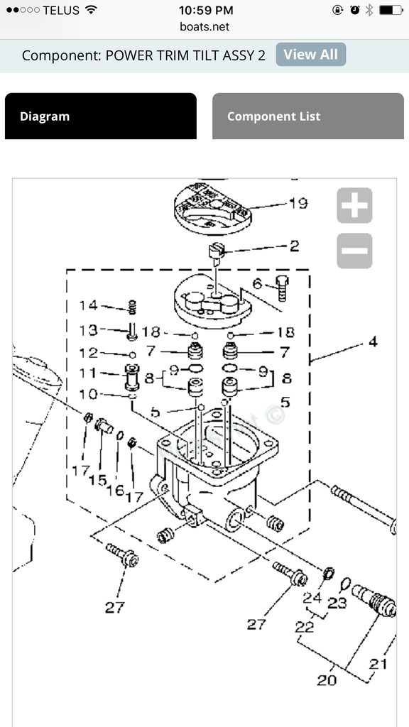 [/IMG]
Well issues with the dealership again. (2004 Vmax HDPI) Took my trim tilt unit in to get weeping seals replaced. Came out of the shop with the trim not holding back when in reverse. I have read through the posts and it is obviously the seat balls in the pump assembly. My problem is that I did not take it apart so I do not know where the small and the large balls are placed. One small ball is missing after the repair at the certified Yamaha dealer.... And it seems two parts (piston shuttles) 7&8 on the parts diagram where installed upside down in the holes with no balls under them as in the parts schematic, and one mystery o ring from where only the mechanic knows. As you can see in the first picture one of the seat balls was in a gear, shake my head.
[IMG]
 [/IMG]
The shuttle two valves in the picture below appear to be installed upside down, no balls under them, should they be the large or the small balls? The parts diagram is a bit confusing regarding the shuttles / valve sub Assy. There are two pieces in the parts schematic but mine appear to be one solids piece, perhaps pressed together?
[IMG]
 [/IMG]
Any way does anyone know if the small balls go under the valves, or do the larger balls go under the valves with the smaller on top? (Small 5 or 18 on the parts diagram?)
Picture of the Shuttles
[IMG]
 [/IMG]
Part diagram does not show if the balls are small or large and the that the valves are two pieces
[IMG]
 [/IMG]

Comment