Buy Yamaha Outboard Parts

Announcement

Collapse
No announcement yet.

99Yam help needed

Collapse
X
 
  • Filter
  • Time
  • Show
Clear All
new posts

  • 99Yam help needed

    Do you have a clamp on ammeter?

    If so, does your motor have easy access so that you can measure the AC amperage that is flowing from your lighting coil to your R/R at say 1500 RPM?

    And after you have measured the AC current can you also measure the DC current to the battery?

    Thanks in advance.


  • #2
    Yes I do have several amp meters.
    one will measure AC and DC
    when it stops raining here I will see how hard it is to get to those wires.
    I will likely be a few hours.

    My internet has been down for a few hours while I was being switched to fiber.
    Got 300 in place of the 6 I had over copper wires

    Comment


    • #3
      thinking about this some, if the RR bleeds off excess voltage to ground, I would think the lower voltage Dc to battery would be less current than the AC.
      and a lot would depend on what state of charge the battery was at that time also.
      a run down battery would take more current into it

      Comment


      • #4
        I am still on copper lines. No fiber in my future.

        Comment


        • #5
          Current from alternator equals current used by motor electrics plus current going into battery, so state of charge doesn’t matter (but changes as motor runs).
          If you really want to know what current the regulator wastes in % then measure everywhere using AC ampere meter (like with like). Test a simple rectifier circuit , AC amp in and DC amp out don’t come out exactly the same because the units aren’t.

          Comment


          • #6
            some of these old 2 strokes did not use much power once started.
            no electric pumps(excepte for T&T)
            ignition system produces their own electrics.
            I was also thinking about the lower voltages after RR, but shunting the overvoltage to ground, I am not sure if that is the AC side or the DC

            Still raining here, but not heavy.
            about 2.25 inches since around 2pm

            Comment


            • #7
              Just about forgot about your request,
              but took some readings just now at 1500 RPM.

              there is one green with white stripe wire heading into the RR, (the 2 greens are tied together and hooked to a blue and the green/w)
              it read 4.8 to 8.4 AC amps, just changing back and forth
              the Positive cable to the read 2.2 amps DC

              Comment


              • #8
                Thanks. Wondering why it is changing back and forth.

                I have a three phase motorcycle R/R connected to a three phase PMA. The AC current is nil but steady when the R/R is providing a DC amp or so to a battery. AC current goes up as a DC load is applied.

                With the Yamaha single phase R/R connected to a single phase PMA, the AC current is about a steady 20 amps when the DC load is about an amp or so. If the DC load goes up the AC current goes down.

                The more I look into this stuff the more I don't understand what in the hell is going on. Frustrating.

                Comment


                • #9
                  Originally posted by boscoe99 View Post
                  Thanks. Wondering why it is changing back and forth.

                  I have a three phase motorcycle R/R connected to a three phase PMA. The AC current is nil but steady when the R/R is providing a DC amp or so to a battery. AC current goes up as a DC load is applied.

                  With the Yamaha single phase R/R connected to a single phase PMA, the AC current is about a steady 20 amps when the DC load is about an amp or so. If the DC load goes up the AC current goes down.

                  The more I look into this stuff the more I don't understand what in the hell is going on. Frustrating.
                  I do not understand what PMA stands for.(Edit guessing Permanent magnet Alternator)
                  how and where are you measuring the nil 3 phase current? edit(phase to phase or phase to ground maybe
                  delta or Y system?)
                  and the single phase PMA AC and dc currents?

                  and what are you measuring the currents with? your scope?

                  I have no idea why my AC amps were hunting while the DC was steady

                  as the DC load goes up on your3 phase set up the AC should increase, and it does.
                  not sure why the single phase AC amps would drop when DC amps go up unless it has to do with where the amps reading are being taken
                  Last edited by 99yam40; 09-04-2022, 09:45 PM.

                  Comment


                  • #10
                    Yes. Permanent Magnet Alternator. Like the electrical generation system on your Yamaha.

                    Using digital meters to measure AC and DC current.

                    Not a clue as to what is going on inside those gizmos.

                    Comment


                    • #11
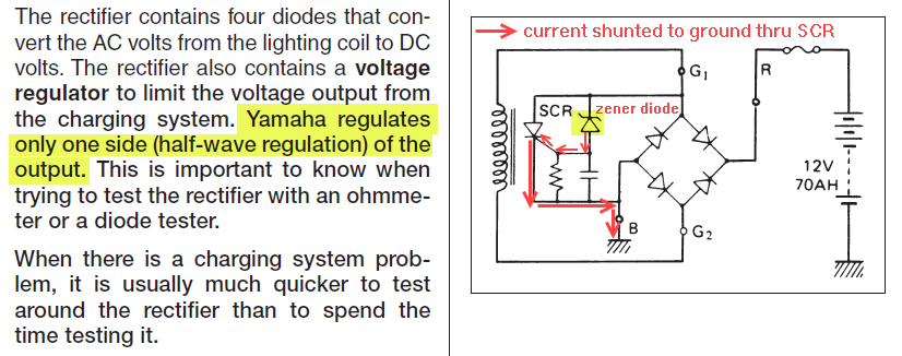
                      Yamaha shunts half of the AC sine wave to ground to keep the voltage down.

                      Seems that others shunt the DC side.

                      Comment


                      • #12


                        I would think Yamaha would still need to shunt the DC side to get it down to 13V

                        clamp on meters or inline current meters?
                        and what/where are you measuring it at?

                        I used Fluke clamp on units when I measured mine.
                        I was asking what the alternator 3 phase was .
                        delta or Y configurations and what wires from them was being measured

                        delta or y phase - Bing images
                        Last edited by 99yam40; 09-04-2022, 11:04 PM.

                        Comment


                        • #13
                          Clamp on meter.

                          3 phase is delta wound. A to B, A to C and B to C were being measured.

                          Comment


                          • #14
                            how were you reading 20 amps between all 3 phases?
                            I am having a hard time envisioning the hook up.
                            there are 3 wires coming out of the PMA & those go into the RR
                            Maybe you just clamped onto each of those 3 individual wires and they each read 0 amps?
                            Or maybe you were measuring between phases some how?
                            did you measure any ground current somewhere?
                            unless the system is referenced to ground somewhere, I do not see how excess would be able to be shunted off to ground.

                            Now a Y configuration with the center point grounded would work


                            on the single phase set up
                            I would guess that most all of that 20 AC amps were being shunted to ground, and very little was being used to create that 1 amp of DC.
                            as the DC load was added, less AC was shunted off to ground and more of it was used to create the DC called for.

                            Comment


                            • #15
                              Originally posted by 99yam40 View Post

                              I would think Yamaha would still need to shunt the DC side to get it down to 13V

                              Comment

                              Working...
                              X