99yam. It surprised me. Frequency was 18 ~ 20 Hz. I thought it would be much more than that.
Announcement
Collapse
No announcement yet.
Constant Voltage Alternators
Collapse
X
-
I am surprised it was not khz, I guess it does not need to be that fast to build up the magnetic field in that alienator.
18 -20 times a second should be fast enough to adjust the voltage/current
it still would be interesting to see if it was a square wave.
with it being DC it would have to be
I just rechecked that DC speed con*****er just to make sure and it read from 4Khz to 14khz.Last edited by 99yam40; 03-09-2022, 07:07 PM.
Comment
-
I have used them many years ago
matter of fact I have 2 old ones I found in my garage that the batteries leaked and messed up things
why?
I have a feeling I have no idea how to set up any newer one,
but I would think setting the voltage and width of pulse should do somethingLast edited by 99yam40; 03-09-2022, 09:19 PM.
Comment
-
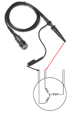
I have been reading the owners manual of one and watching lots of YouTube videos. No where does it talk about where to connect the probe. Say for instance if I just want to view the voltage and waveform of a 120 volt wall outlet. Lots of cautions but no clear cut directions.
Comment
-
well. to measure the circuit, you would need to attach the leads to what you want to measure.
DC would be to the + and - or across some part of the circuit you are trying to get a reading on
AC would be to the hot and neutral, or phase to phase, or phase to ground if the circuit is referenced to ground somewhere.
the leads are rated like 1X( full voltage), 2X ( 1/2 voltage) 10X 1/10th voltage), etc to reduce the amount of voltage hitting the scope
Look at what the scope settings are and start out on a high setting and lower it down once running to get the wave form to show you the way you want it to
just do not send too high of a voltage into it for the setting.
you have a link to the manual of the one you are trying to use?Last edited by 99yam40; 03-09-2022, 10:32 PM.
Comment
-
Just ran the frequency test again. The frequency varies (increases) with the load. Makes sense I guess since the regulator is pulsing the voltage at a higher rated to facilitate higher current flow.Originally posted by 99yam40 View PostI am surprised it was not khz, I guess it does not need to be that fast to build up the magnetic field in that alienator.
18 -20 times a second should be fast enough to adjust the voltage/current
it still would be interesting to see if it was a square wave.
with it being DC it would have to be
I just rechecked that DC speed con*****er just to make sure and it read from 4Khz to 14khz.
Comment
-
The test probe is a coaxial wire. Outer portion is grounded to the ground plug of the cord that powers the scope. I presume that I would not use the ground clip on the probe and merely touch the tip of the probe to the hot wire. ???Originally posted by 99yam40 View Postwell. to measure the circuit, you would need to attach the leads to what you want to measure.
DC would be to the + and - or across some part of the circuit you are trying to get a reading on
AC would be to the hot and neutral, or phase to phase, or phase to ground if the circuit is referenced to ground somewhere.
the leads are rated like 1X( full voltage), 2X ( 1/2 voltage) 10X 1/10th voltage), etc to reduce the amount of voltage hitting the scope
Look at what the scope settings are and start out on a high setting and lower it down once running to get the wave form to show you the way you want it to
just do not send too high of a voltage into it for the setting.
you have a link to the manual of the one you are trying to use?
Comment
-
-
It has been a very long time since I used one.Originally posted by boscoe99 View Post
The test probe is a coaxial wire. Outer portion is grounded to the ground plug of the cord that powers the scope. I presume that I would not use the ground clip on the probe and merely touch the tip of the probe to the hot wire. ???
I looked at the old units I have and I am confused also on where that little grounding probe is suppose to hook onto.
they look like they are attached to the coaxial shield of the probe wire.
But these old units ran off of internal rechargeable batteries and the 120V plug is just a 2 prong , no ground.
So I would guess they hooked to a good ground to help shield the signal wire.
the probes have 1 M ohm stamped on them.
I did not see any 1X or 10X on them
post up a model # and I will look around on line to see if I can find any infoLast edited by 99yam40; 03-10-2022, 01:22 PM.
Comment
-
a very good U tube on scope probes
Oscilloscope Probes: What You Need to Know - Bing video
the ground clip on the end of probe should be hooked to the body of the things you are taking measurement on to keep ringing at a minimum( interferance of the signal)
another one on scope settings
How to Use an Oscilloscope - Bing videoLast edited by 99yam40; 03-10-2022, 01:47 PM.
Comment


Comment