Buy Yamaha Outboard Parts

Announcement

Collapse
No announcement yet.

Constant Voltage Alternators

Collapse
X
 
  • Filter
  • Time
  • Show
Clear All
new posts

  • Constant Voltage Alternators

    My FAA handy dandy bible says that alternators for light airplanes are of the constant voltage type. Airplane alternators being more or less the equivalent of car/truck alternators.


    Tests in my laboratory seem to indicate that the output voltage is being held constant as an electrical load is applied and removed. See photos below.

    Would you folks agree that boat/car/truck/airplane alternators are doing what they can to maintain a constant voltage? Reason why I ask is that a somewhat reputable authority (or so I thought) said they are not constant voltage.


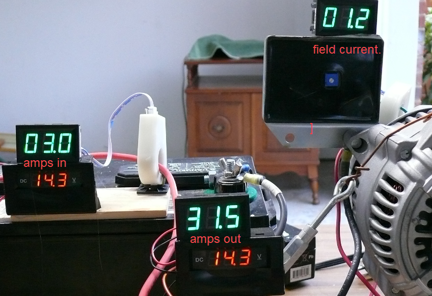
    ​​​​​​​

  • #2
    This post was held in limbo for one day for some strange reason.

    Comment


    • #3
      Originally posted by boscoe99 View Post
      Would you folks agree that boat/car/truck/airplane alternators are doing what they can to maintain a constant voltage?
      I am not sure what "constant voltage" is intended to mean, in this context.

      It is my understanding,
      that the regulator is designed for a single target voltage,
      imposed as an upper limit.

      If/when the electrical load on the alternator is high enough,
      the system voltage may be slightly below the target voltage,
      so in that respect the voltage is not always "constant".

      But certainly an "ordinary" alternator
      is not intentionally controled to one voltage at one time,
      and to a different voltage at another time.

      Comment


      • #4

        Looks like:
        amps & voltage measured into battery
        amps & voltage measured out of alternator (cannot see the CT)

        I guess the battery is fully charged at the start of testing(0 amps into bat and 0 out alt with the same voltages?
        And all you are changing is the load being drawn.

        your readings show the voltage very close to constant.
        if the voltage readings were an extra decimal or 2 it might show even closer.
        the meters have to change at some point to round off to give 10ths

        Comment


        • #5
          Originally posted by fairdeal View Post

          I am not sure what "constant voltage" is intended to mean, in this context.

          It is my understanding,
          that the regulator is designed for a single target voltage,
          imposed as an upper limit.

          If/when the electrical load on the alternator is high enough,
          the system voltage may be slightly below the target voltage,
          so in that respect the voltage is not always "constant".

          But certainly an "ordinary" alternator
          is not intentionally controled to one voltage at one time,
          and to a different voltage at another time.
          I interpret "constant voltage" to mean whatever set point the regulator is designed to. If it is 14.5 volts then the regulator should make an adjustment to the alternator field so as to maintain 14.5 volts as the load on the alternator varies. Recognizing that the voltage may vary somewhat based on the load.

          Usually a fixed value. But the regulator shown in the photos is adjustable. Manually.


          For "ordinary" alternators of course. When it comes to ECU con*****ed alternators, as might be found in late model cars, all bets are off.

          Comment


          • #6
            Originally posted by 99yam40 View Post
            Looks like:
            amps & voltage measured into battery yes
            amps & voltage measured out of alternator (cannot see the CT) yes but what is CT?

            I guess the battery is fully charged at the start of testing(0 amps into bat and 0 out alt with the same voltages? Not fully charged but mostly. The current flow into the battery will drop to less than a tenth of an amp when it is fully charged.
            And all you are changing is the load being drawn. Yes.

            your readings show the voltage very close to constant. Don't know if the variance is due to the regulator or the cheap chinese meters.
            if the voltage readings were an extra decimal or 2 it might show even closer. Yes.
            the meters have to change at some point to round off to give 10ths
            What do you mean by CT?

            Comment


            • #7
              It was interesting to me to note how little the field current needed to be increased in order to greatly increase the output of the alternator.

              Comment


              • #8
                Interesting test. Are you changing loads ? What brand is your alternator ? How are you testing and its application. I have a FLUKE 88A "the bad boy" and FLUKE 77 lll and a host of other electrical testers. I've never seen a alternator change amps, bt not volts.. Dosnt make sense. Yes at higher rpms higher amps are possible but the voltage is the con*****ing factor. Same for solar, gensets and the small wind gens I've worked on sail boats.. Can you install a Shunt and retest ?

                Comment


                • #9
                  Originally posted by boscoe99 View Post

                  What do you mean by CT?
                  Current Transformer, but those are normal for AC, maybe it should be a DC shunt instead.

                  that white thing the red pos battery cable is running thru made me think CT

                  but my Fluke 337 clamp on Meter reads both AC and DC amps and it is not a shunt

                  what are you using to vary the load?
                  what is the amp rating on that alternator?

                  the current going into the battery was steadily going down, that is why I was wondering about the battery being fully charged at the beginning

                  I read your post/ question again, and I have always thought the regulators were voltage regulators not current regulators.
                  apparently not much current change is needed to make the magnetic field strength change
                  Last edited by 99yam40; 03-08-2022, 11:47 AM.

                  Comment


                  • #10
                    Holy Sh__ I just went to look at some fluke meters. And I ain't so proud anymore. LOL. Damn,, you can get Crazy with these. They are the best in the biz. I don't yearly get mine calibrated
                    to military specs.. Sigh,, its only green toilet paper anyway,, right ?

                    Comment


                    • #11
                      I still have one of my Fluke 87s that still works.
                      we use to have them sent in to verify calibration when working in the Meter and Relay group.
                      Not many had that need

                      I had a hand in them creating the T5-1000
                      needed one for the operators and other techs to safely read over 800VDC on the Cl2 cells in our plants, so they came out with one certified to 1000VDC for us.
                      I do not think they changed much (maybe higher voltage rated components) to get the certification that it could be used at those voltages instead of just 600vdc

                      Comment


                      • #12
                        Originally posted by 99yam40 View Post

                        Current Transformer, but those are normal for AC, maybe it should be a DC shunt instead.

                        that white thing the red pos battery cable is running thru made me think CT

                        but my Fluke 337 clamp on Meter reads both AC and DC amps and it is not a shunt

                        what are you using to vary the load?
                        what is the amp rating on that alternator?

                        the current going into the battery was steadily going down, that is why I was wondering about the battery being fully charged at the beginning

                        I read your post/ question again, and I have always thought the regulators were voltage regulators not current regulators.
                        apparently not much current change is needed to make the magnetic field strength change
                        Those are what I know to be Hall Effect ammeters. Similar to a clamp on meter I believe. https://www.amazon.com/gp/product/B0...?ie=UTF8&psc=1

                        The loads are just nichrome wire that I wound into coils. Three coils each with its own on/off switch.

                        Alternator is rated for 125 amps.

                        I agree. Voltage regulators. Trying to keep the voltage constant as the loads on the alternator change.

                        Comment


                        • #13
                          My next objective is to use an oscilloscope to see how many times the regulator pulses current through the field coil. I would expect it to be thousands of Hertz.

                          Comment


                          • #14
                            Originally posted by boscoe99 View Post
                            My next objective is to use an oscilloscope to see how many times the regulator pulses current through the field coil. I would expect it to be thousands of Hertz.
                            interesting.
                            have you tried reading KHZ with a regular meter on that DCV to field coil
                            this reminds me some of the variable speed DC motor con*****er I bought not long ago
                            I put 29 VDC into it out of a 120VAC to/29VDC out power supply and measured the DC output while running the linear actuator 18VDC motor.

                            At low dcv output read KHZ around 5 and at full output it was around 14KHZ.
                            it will drive a brushed dc motor, but not a brushless

                            and there were Hall effect sensors used in a lot of the controls on our large rectifier and chopper units
                            and on the measurement devices on the output busses reading up to 80Kamps

                            if I remember correctly, they measured the current flow it took to cancel/nullify the magnetic fields around the buss.
                            I never did fully understand most of the stuff I worked on and around
                            Last edited by 99yam40; 03-08-2022, 07:32 PM.

                            Comment


                            • #15
                              Hmmm. Have not thought of using a frequency meter. Will give that a go. Thanks for the suggestion.

                              Understanding electronics is tough.

                              Comment

                              Working...
                              X