Buy Yamaha Outboard Parts

Announcement

Collapse
No announcement yet.

F40 rebuild yes or no ?

Collapse
X
 
  • Filter
  • Time
  • Show
Clear All
new posts

  • #31
    Hi guys!

    Thanks for answers!

    Yes, YAMAHA is really expensive on most parts, others I donīt think to be very expensive (at least here in EU, from all stuff I already ordered here on this site for this project just found 2 bushings and 1 o-ring cheaper here in PRT and now Euro currency worth much less which increased the costs of my rebuild but worth anyway because I have a friend that will brings me the parts)
    On my local Yamaha dealer they said that this year most parts increased 1 up to 3% Again!?!?!?
    An example in Euros for the head gasket:
    Here in PRT for the genuine head gasket 78€, on this site 38€, from Mercury 21€

    Yes, boating is not cheap getting started just on fuel price (fortunately a little better now)

    The relays of an old jonny/rude (or other) may be a good option and I'll have look on that but the above schematic pleases me.

    How many amps should have the circuit breaker?

    Yesterday I've been talking with a mechanic that rebuild 2 of these motors with +/- 3k or 4k hours (maybe more, no clocks) and he said after +/- 500 hours bearings failed again on both.
    He said that crankshafts have been checked/measured and he said the bearings oil clearance have been measured with plastigage. I've been a little worried...

    Comment


    • #32
      on the motor feed I would not worry to much, the motor has a thermal overload.
      the control side 15 amps is plenty.

      Comment


      • #33
        Hi!

        Last Friday received almost all parts from motor that were painted on a friend auto shop garage (still miss the apron and hood) so on monday started the assembly of motor and power head.

        All seemed to go OK, just the carbs assembly were missing when I remember “why not a leak down test and compression test before the first attemp to power up the motor”

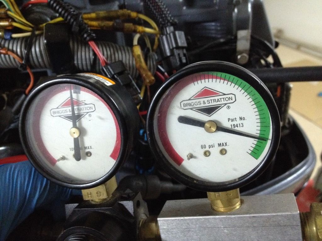
        So I did a leak down test… my briggs and straton tester donīt show percentage leakage but all 3 cyl are on the beginning of green side scale, #2 almost donīt have any leaks.

        Then did a compression test and got a surprise… 60 psi on #1 cyl “what is this!?!?!? Canīt be right” it was my thought, #2 same thing +/- 60 psi compression and on #3 I canīt use my compression tester as the pipe isnīt all from rubber and have a metal tip of +/- 10 “4in” and canīt twist it on the #3 spark plug hole because of bottom cowling.

        Did the leak down test again and same results on all 3 cyl than did again a compression test on #1 and #2 cyl and same results…

        Tested compression gauge and diference from my air compressor gauge is very few, the adaptor use on spark plug bore is the same used on compression and on LeakDown test, so no leakes on thread.

        New head gasket, it seals on LDT so canīt be here the prob
        New piston rings, it seals on LDT so canīt be here the prob
        Valves cleaned and seats polished, it seals on LDT so canīt be here the prob
        Block and head shaved/resurfaced,
        cylinders polished on a auto machine shop (no scores)
        Every time I’ll power the starter will make oil pump work so shoudnīt be lack of lube in cyl walls

        Whats is this!?!?!?

        Whats left?

        I just can see a cause:

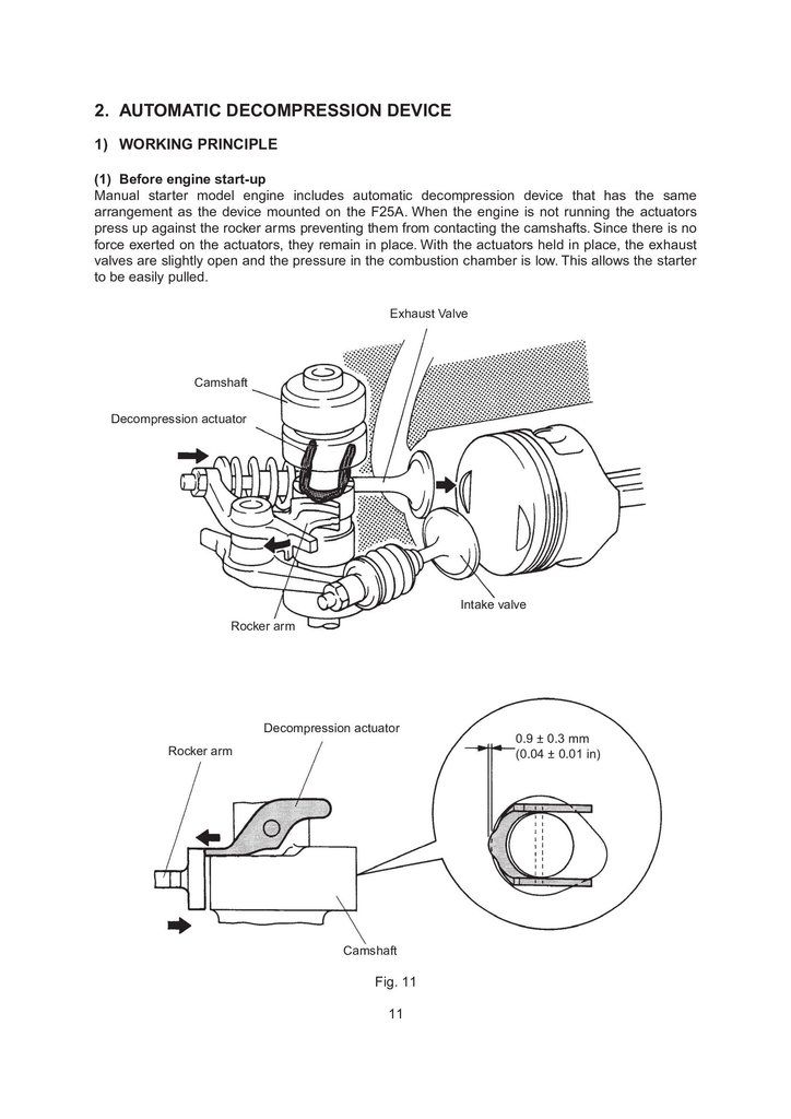
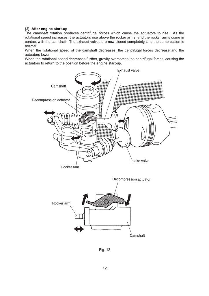
        I’m using a camshaft from a Manual Start motor that have a decompression actuator for easily start motor manually but my motor is electrical start.

        But some guys use electrical and manual start on these motors
        That decompressors were moving freely when instaled the camshaft and should rise when starter rotate the flywheel ( my thought) as I do it constantly and quickly then a pull of manual start.

        SM donīt refer to diferent compression values on Manual Start motor (with decompressor device)

        Wrapped a rope around the flywheel for manual start and was very easy pull the rope and rotate the flywheel, looks like my F4, even with that decompresson actuators should be that easy?

        My 30X3 is MUCH more hard to pull compared with this motor.

        Suggestions are wellcome!


        This are the results of LDT on #1 and #3 cyl, #2 is even better, little above where green scale starts.

        Comment


        • #34
          Been there,with same issue.Remove the decompression actuators,and i think it will be ok. Cant remember if i changed the camshaft,but probarly i removed the actuators-cant harm anything anyway.

          Comment


          • #35
            Today removed the decompression actuactors...

            Problem solved!

            #1 and #2 175psi #3 donīt know yet and canīt use my tester

            Comment


            • #36
              I would have left the decompression actuators in place.
              they were working as designed and you never know if you may actually have to pull start it.
              why do folks redesign everything?

              much above about 300 RPM the actuators release the ex valve rocker so the valve will fully close.
              it does not hold the valve open enough to hurt anything at cranking speeds.

              Comment


              • #37
                Hi Rod!

                Originally posted by rodbolt17 View Post
                I would have left the decompression actuators in place.
                That was what I intended (just in case... other wise I had them removed when installed the camshaft on the head) but for any reason that I donīt know didnīt worked!!!

                Seems ARNY had the same experience!

                The decompression actuators were moving freely but using the electrit start seems that havenīt raise while cranking and that was the reason of low compression.

                What would be you recomendation?

                (but now I canīt get back as unfortunately I broked one of the actuators while removing them and arenīt offered spares.

                I'm using Yamaha and Mercury (much, much better) SM and none of them refer to a diferent compression ratio for electrict vs manual start.

                Iīve been very surprised how easy is pull that thing with the actuators.

                Other thing I've noticed is that Mercury donīt use much a DVA adapter, most of the time they recomend measure ohm resistence to test devices.

                Each one is better??? IDK

                Comment


                • #38
                  Hi!

                  Finally today had time to finish the 7 pin wiring to the tiller using some type of bullet connectors since I didnīt found a female 7 pin connector at resonable price and the trim wiring using 2 automotive SPDT relay however I still miss the trim motor but all working good.

                  Then assembled the carbs and tryed fire the thing… guess what?

                  Started a the 1st turn of the key however #2 carb was leaking and #3 accelarator pump nozzle was not working. Carbs were cleaned about 6 months ago and on the shelf since then.

                  #2 solved cleaning idle jet but on #3 not even with compress air and brake cleaner.Then resorted to the data gently gave by Boscoe and drilled the carb accordingly marine technical guide and problem solved! Thanks Boscoe!

                  One thing that was concern me was the oil pressure. SM refere to min 21PSI at idle (got +/- 50PSI at idle) which sound good to me but I was not expecting so high pressure.

                  When ordered the main bearings ordered the black bearings which are the ones recomended by the block letters and just after that found that the blueīs are with more thickness.

                  For plastigauge SM refer to 0.012mm up to 0.044mm oil clearance of main bearings. I had 0.035 but I wanted better so thought that worth buy the blue bearings and I did it. You know what? BS…. No diference at all.

                  What care should I have in first hours of operation?

                  Already balanced the carbs using na inductive tach and all seems to be working good but I just will test motor under load/on the water in a couple of months.

                  There is one thing I couldnīt solve yet and I’ll need you help please.

                  How to wire the tach?

                  Where the Green wire of the 7 pin conector is connected???

                  Comment


                  • #39
                    the dark green goes to the tach send terminal.

                    Comment


                    • #40
                      Hi!

                      Found the solution for the tach wiring.

                      The green wire male connector from 7 pin connector goes to...? the only female connector available!

                      LOL now seriously!

                      I already had tested with green/white and white/green wires coming from stator and no sucess... with one of that wires connected to the tach the motor dont even start, then tried to connect both the tach and the above wires that are connected to the R/R but rpmīs reading were faulty.

                      I've been googling for F30 F40 tach wiring without sucess then remember why no try my search with F25 that use same stator, flywheel, R/R etc and found the answer this time...

                      The green wire goes to the gray wire of R/R (the only one that was unplug)
                      Now tach is working!

                      In fact when assembling the electrical wiring that gray wire let me curious for what to be because since had no place to connect (in fact it does)

                      At the time tried Mercury SM because is much more detailed but didnt got the answer so I forgot this thing but now we know.

                      Soon I'll try to post a few fotos or video.

                      Thanks

                      Comment

                      Working...
                      X